AMR map-change acceptance: test relocalization and routes
A map that loads is not a production release. Classify the change, then verify map alignment, relocalization, representative routes, task endpoints, failure response and the safety boundary.
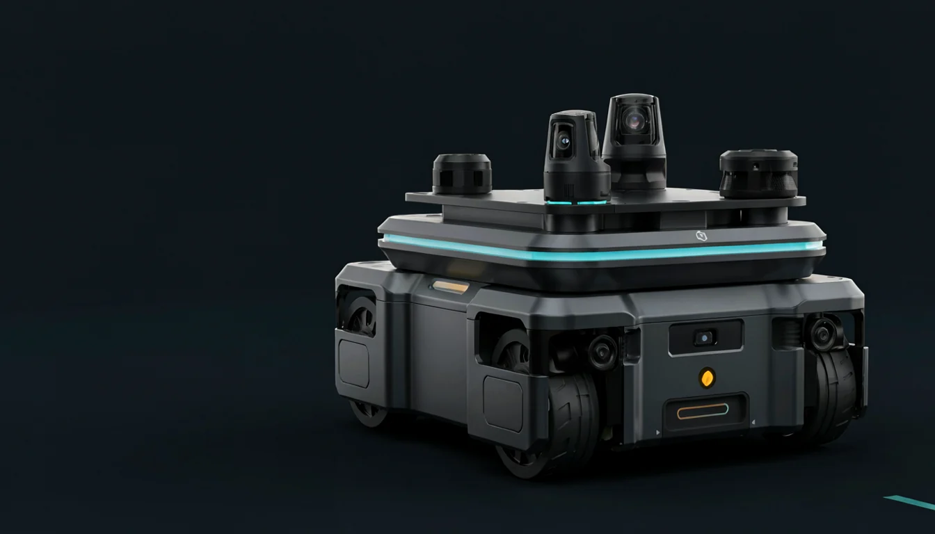
The short answer: do not release an AMR after a rack, station, aisle or navigation change merely because the new map loads or one mission completes. First decide whether the change belongs to a temporary-obstacle layer, station and zone semantics, permanent site geometry, or the localization sensor and algorithm chain. Then test the affected layers: map-to-site correspondence, startup and forced relocalization, representative routes, task endpoints, failure response and the operating-zone safety boundary. Keep the preceding baseline recoverable.
Map correctness, localization and mission completion are different evidence
The Nav2 Map Server loads a map file and publishes it in a named map frame. The Nav2 state-estimation guide separately describes the global map→odom correction and the smooth, continuous odom→base_link transform; it also identifies AMCL as localization in a static map. This interface boundary is operationally useful. A successfully loaded file proves a configuration path. A smooth pose does not prove the global hypothesis is correct. One completed route says little about other stations, traffic interactions or recovery paths affected by the change.
NIST's map-quality research compares structural features in a robot-generated map with a ground-truth map and notes that real maps may be incomplete, distorted or noisy. A site need not reproduce that particular algorithm to retain the principle: compare the production map with an independently confirmed layout or measurement datum. The localization output that generated the map should not become its own only ground truth.
Four change levels set the regression scope
| Change level | Typical examples | Preferred treatment | Minimum regression |
|---|---|---|---|
| Temporary obstruction | Short-lived staging, people at work, a temporary pallet | Keep the baseline map; use local perception, routing and site controls | Detection, stop/slow response, detour and recovery on affected routes |
| Semantic or mission change | Stations, wait points, one-way, no-go or speed zones | Update mission, traffic or zone configuration without disguising semantics as geometry | Related routes, endpoints, traffic conflicts, permissions and safety zones |
| Permanent geometry change | Moved racks, fences, walls, aisle width or fixed equipment | Edit or rebuild the map and re-establish its site datum | Relocalization, changed and connected routes, clearance, endpoints and recovery |
| Localization-chain change | Sensor, extrinsic, wheel size, algorithm, firmware or critical parameter | Treat it as a measurement-chain change, not an ordinary map edit | Localization ground truth, all representative routes, degradation, tasks and safety |
Do not bake every temporary pallet into the static map: a short-lived condition then becomes a lasting planning constraint. Conversely, do not leave a permanent rack move entirely to local obstacle avoidance while global localization still interprets an obsolete structure. Classification is how the test scope follows the real impact without turning every minor edit into a full-site campaign.
An executable map-change regression workflow
- Freeze the change record.State what moved, when, by whom, and which zones, stations, routes, vehicles and shifts are affected. Separate physical geometry, semantic configuration and localization-chain changes.
- Save the preceding baseline and recovery conditions.Retain map files, origin and resolution, stations and zones, localization parameters, sensor extrinsics, software/firmware versions and applicable vehicle groups. ASTM F3327-23 calls for the hardware, software, localization method, speed/acceleration, environment map and settings needed to contextualize and recreate an A-UGV test. A rollback therefore restores a reproducible configuration set, not merely an image.
- Check map-to-site correspondence.Use an approved layout, measured datums or independent positioning ground truth to inspect permanent structure, traversable boundaries, narrow aisles and critical intersections. Confirm that export or editing has not shifted the origin, scale or orientation.
- Challenge initialization and relocalization.Power up from representative positions, headings and repetitive areas. Under controlled safe conditions, force a localization loss or relocate the vehicle. Record time to the correct hypothesis, failures, false localization, human intervention and the evidence required before mission continuation—not just a screenshot of a confidence value.
- Run changed and connected routes.Following the application-oriented intent of ASTM F3244-21, use relevant boundaries, clearances, obstacles and communication impairments in a defined area. Cover normal and alternate routes, yielding, stop-and-resume and real payloads. Retain success, time, stops, detours, interventions and failures by route and condition.
- Verify task endpoints.After navigation passes, test pickup/drop-off, charging, doors, lifts, conveyors and the required docking outcome. A mobile manipulator must continue to a workpiece-coordinate result; our mobile-manipulator docking acceptance guide covers that adjacent layer.
- Test the wrong-hypothesis response.Occlude important features, create ambiguity in repetitive aisles or introduce a bounded local mismatch. The system should slow, stop, cancel, relocalize or hand over rather than continue into a station or traffic zone with a known-bad global pose.
- Release in stages and define triggers.Start with a small vehicle group and restricted routes across real shifts and traffic, then expand. Define when rack/station moves, wheel or sensor maintenance, software updates or recurring localization faults trigger a local retest or a wider regression.
A localization confidence value is not ground truth
Particle spread, match score, covariance and vendor health states can support monitoring and trigger a degraded mode, but each belongs to a particular algorithm, sensor set and configuration. The same value may not represent the same physical error after a map, extrinsic, algorithm or environment change. Acceptance should establish the relationship among independent ground truth or a physical task result, reported localization state and system action. Include reachable site conditions such as repetitive structure, feature-poor regions, occlusion, wheel slip and initial-heading error.
Minimum release evidence pack
- Change reason, affected area, change level, approver and implementation window;
- old and new maps and semantics, origin/resolution, localization parameters, sensor extrinsics and applicable vehicles;
- independent map-to-site comparison, critical datums and unresolved differences;
- raw startup, controlled delocalization, false-localization detection and recovery records;
- representative route, payload, traffic, endpoint-task and failure-scenario results;
- failure criteria, release scope, monitoring period, rollback conditions and last usable baseline.
Safety boundary: ISO 3691-4:2023 addresses safety requirements and verification for driverless industrial trucks and their systems, and notes that operating-zone conditions significantly affect safe operation. Map and localization regression is performance evidence, not safety-function validation. Changes to physical aisles, protective zones, speed, human access or the operating area still require review by the responsible risk and conformity parties. ISO currently shows this edition under revision, so projects should confirm the formal edition applicable at delivery and in their jurisdiction.
Frequently asked questions
Does a temporary pallet require a new AMR map?
Usually not immediately. Confirm that it is genuinely temporary, detectable and does not change the safety operating zone, then test stopping, detour and recovery. A persistent obstruction that changes route boundaries should become a controlled semantic or geometry change.
What is the minimum test after a new map loads?
Check the map against site datums, challenge startup and recovery from localization loss, run the changed and connected representative routes, and verify critical endpoints, failure response and rollback. Loading only proves the file and service path.
Can an AMR be released when localization confidence exceeds a threshold?
Not from that value alone. Relate the threshold to independent ground truth, task tolerance and system action, then reconfirm it after map, sensor or algorithm changes. Test how false localization and low confidence invoke a degraded response.
Does a small map edit require every fleet vehicle to be retested?
It depends on whether vehicles share the same map and localization configuration. A representative vehicle and restricted route can lead a staged release, but each affected configuration family needs coverage when sensors, parameters or footprints differ.
Sources
These primary sources support the material facts and engineering boundaries discussed above.
- Nav2 Documentation — State Estimation
- Nav2 Documentation — Map Server
- NIST — Map Quality Assessment
- ASTM F3327-23 — Standard Practice for Recording the A-UGV Test Configuration
- ASTM F3244-21 — Standard Test Method for Navigation: Defined Area
- ISO 3691-4:2023 — Driverless industrial trucks and their systems
Evaluating robot control, bimanual manipulation or a mobile platform?
Talk to Matrix Dimension →