How to accept machine-vision lighting: test the operating window
Lighting is accepted when target features remain separable across real parts, motion, position, ambient light and maintenance states—and the downstream inspection still meets its task criteria.
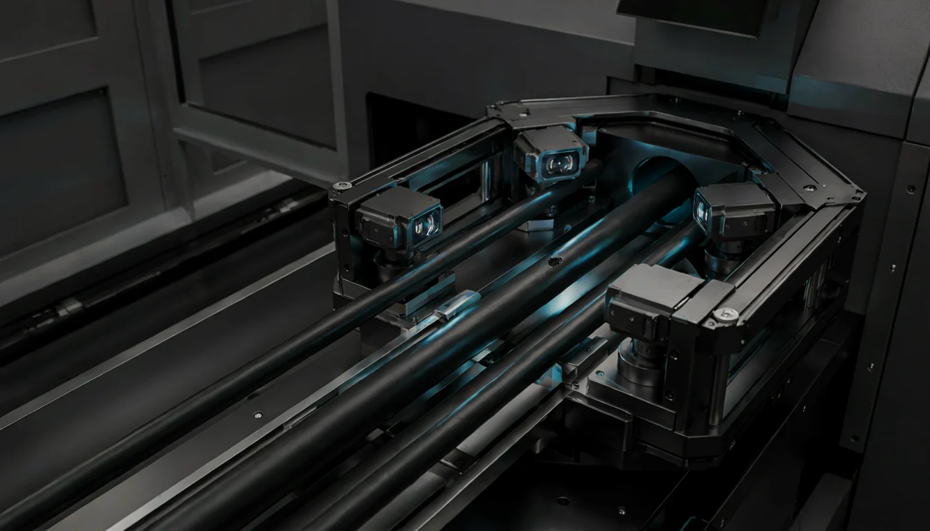
The short answer: do not accept machine-vision lighting from a single “best” image. Define the optical interaction that makes each target feature visible, then freeze source–part–lens geometry, wavelength or polarization, exposure and trigger conditions. Run a factory acceptance test (FAT) and an on-line site acceptance test (SAT) with representative good parts, defects and reachable disturbances. Acceptance requires both image-level feature separation and task-level detection or measurement performance to remain inside the agreed operating window.
Define what must become visible before choosing a light
A machine-vision image does not need to look attractive to a person. It needs a stable, measurable difference between the target feature and everything that can be confused with it. The A3/Automate discussion of machine-vision lighting identifies appearance, surface and specular behaviour, positional variation, lighting geometry, wavelength, polarization, continuous or strobed operation and working distance as relevant selection factors. More intensity is not a requirement by itself: saturation, glare, shadow or background texture can erase the feature that matters.
Write an optical hypothesis for each defect class. Is the signal a silhouette, a height or texture change, a change in specular reflection, a colour or material response, or a transmission difference? Backlight is a natural candidate for silhouette; low-angle dark field can direct light scattered by an edge or scratch into the lens; coaxial or diffuse arrangements can control reflections from flat or curved surfaces; wavelength and filters can increase material contrast or reject ambient light. The official KEYENCE lighting selection guide similarly distinguishes bright-field, dark-field, diffuse, backlight and coaxial arrangements. They are candidate mechanisms—not proof that one implementation will meet its inspection target.
Separate four acceptance layers
| Layer | Question | Evidence | What it does not prove |
|---|---|---|---|
| Optical mechanism | Why does the target become brighter, darker or structurally different from its background? | Defect–surface–light geometry, wavelength/polarization comparison and representative raw images | Long-term factory stability |
| Imaging stability | Does the feature remain separable as position, speed, exposure, ambient light and temperature change? | Raw-pixel statistics, saturation/blur/uniformity, trigger timing and stratified disturbance results | Correct algorithm decisions |
| Task performance | With the algorithm and thresholds frozen, are defects detected or dimensions measured to requirement? | False accepts, false rejects or measurement error by defect class and condition | Coverage of every quality attribute |
| Maintainability | After cleaning, replacement or remounting, how is the approved baseline recovered? | Parameter versions, reference artefact, maintenance limits, requalification and rollback steps | Product-standard or safety compliance |
EMVA 1288 is camera evidence—not a lighting-system acceptance
The EMVA introduction to Standard 1288 describes a unified method for measuring and presenting machine-vision camera and image-sensor parameters so that camera comparisons are more transparent. Release 4.0 Linear covers sensitivity, linearity, noise, dark current, spatial nonuniformity and spectral sensitivity, with controlled requirements for the measurement source's geometry, spectrum, polarization and irradiance.
That evidence helps a team understand sensor response under defined conditions. It does not establish that a particular lens, light, installation, part surface and algorithm will reveal a production defect. Treat EMVA 1288 data as a camera-layer input, then validate the complete application with representative samples. “EMVA 1288 camera” should not be presented as a system-level inspection result.
A practical FAT-to-SAT workflow
- Freeze features and acceptance criteria. For every defect class, define the minimum relevant size, location, orientation, surface and severity, plus normal variation that can be confused with it. For metrology, define the edge, datum, tolerance and required measurement uncertainty.
- Build the sample matrix. Cover real materials, colours, gloss, curvature, contamination, position and lots. Include good parts and boundary defects—not only obvious failures. Establish sample truth independently from the vision system under acceptance.
- Screen optical mechanisms. Without changing the algorithm, compare credible backlight, bright/dark field, coaxial/diffuse, wavelength, filtering and cross-polarization arrangements. Record which surface interaction creates the contrast. Select the simplest mechanism that consistently amplifies the target and suppresses the background.
- Freeze optics and acquisition. Record light-to-part and camera-to-part distance and angle, field of view, lens, aperture, focal or working distance, polarizer orientation, source current, exposure, gain, white balance, trigger delay and pulse width. If automatic exposure or gain is permitted, define its range and validate how it changes the decision signal.
- Run a speed-and-environment FAT. The NI lighting guide identifies overhead fixtures, daylight and adjacent task lights as ambient contributors, and discusses high-power strobes, physical enclosures and pass filters as control options. Vary part pose, line speed, ambient-light states, exposure and mounting tolerance. Inspect saturation, blur, shadow, glare and feature separation instead of repeatedly imaging one static sample.
- Run SAT on the production line. Include real transport, vibration, guarding, dust, adjacent stations, shifts and operator workflow. For strobed lighting, measure the relationship among camera exposure, light pulse and part-present timing. Report task results by defect class and condition rather than one pooled accuracy figure.
- Create a maintenance baseline. Retain approved raw reference images, pixel or feature ranges, parameter versions and a reference part or artefact. Define which checks follow cleaning, remounting, light or lens replacement, controller service or model changes—and when automatic compensation must stop for manual requalification.
Minimum acceptance evidence pack
- Defect catalogue, task criteria, sample provenance and independent ground truth;
- Source–part–lens geometry and critical mounting tolerances;
- Exact light, controller, lens, filter, polarizer and camera versions;
- Exposure, gain, aperture, source current, trigger delay/pulse and line speed;
- Representative raw images with saturation, blur, uniformity and feature-separation records;
- Task results stratified by defect, material, position, speed, ambient light and shift;
- Post-cleaning/replacement checks, maintenance limits and parameter rollback path.
Matrix Dimension perspective
The following is an engineering inference from EMVA standards, industry-association material and equipment-vendor guidance: in a continuous-surface application such as a cable inspection platform, illumination, trigger timing and product motion are one measurement chain—not accessories in front of a camera. The durable deliverable is not a parameter set that works at today's threshold, but a reproducible optical mechanism, disturbance boundary and maintenance baseline. For the boundary of what the final inspection can prove, see our inline cable vision acceptance guide. For camera-interface and feature-change validation, see our GenICam 2026.07 integration guide.
Safety and capability boundary: this article does not claim that any Matrix Dimension product has passed a lighting or photobiological-safety certification. High-intensity, strobed, ultraviolet or infrared sources require assessment of exposure, shielding, interlocks and applicable rules. IEC 62471 provides an exposure-limit, measurement and classification framework for photobiological hazards from incoherent broadband sources, including LEDs. The responsible party must determine the applicable requirements from the actual wavelength, radiance, pulse regime, distance and accessibility.
Frequently asked questions
Is image uniformity enough to accept the lighting?
No. Uniformity may matter for metrology or background segmentation, while dark-field inspection can deliberately create localized scattering. Validate feature separation, saturation and blur limits, then false accepts, false rejects or measurement error by defect class.
Is strobed lighting always more stable than continuous lighting?
No. A strobe can shorten effective exposure and overpower some ambient contribution, but its pulse, camera exposure, part position and controller timing must be verified. Thermal, lifetime, human-exposure and driver limits also remain.
Can automatic exposure compensate for source aging and ambient change?
Only after its range, response and effect on defect contrast are validated. It may hold average brightness while changing local saturation, noise or material-to-material contrast, so it does not replace maintenance and requalification.
Why is SAT required after a successful FAT?
FAT rarely reproduces the full transport, vibration, ambient light, guarding, dust, adjacent-equipment and operator variation of the installed line. SAT supplies an independent layer of evidence for the real imaging chain and task result.
Sources
These primary sources support the material facts and engineering boundaries discussed above.
- EMVA — Introduction to the EMVA 1288 camera-characterization standard
- EMVA 1288 Release 4.0 Linear — Standard for Characterization of Image Sensors and Cameras
- Association for Advancing Automation — Machine Vision and Lighting
- NI — A Practical Guide to Machine Vision Lighting
- KEYENCE — Machine Vision Lighting Selection Guide
- IEC 62471:2006 — Photobiological safety of lamps and lamp systems
Evaluating robot control, bimanual manipulation or a mobile platform?
Talk to Matrix Dimension →