AMR obstacle-detection acceptance: test blind zones, not lidar range
Sensor range does not prove complete vehicle coverage. Freeze the vehicle and load envelope, define representative objects, then test the final action under real speed, floor and disturbance conditions.
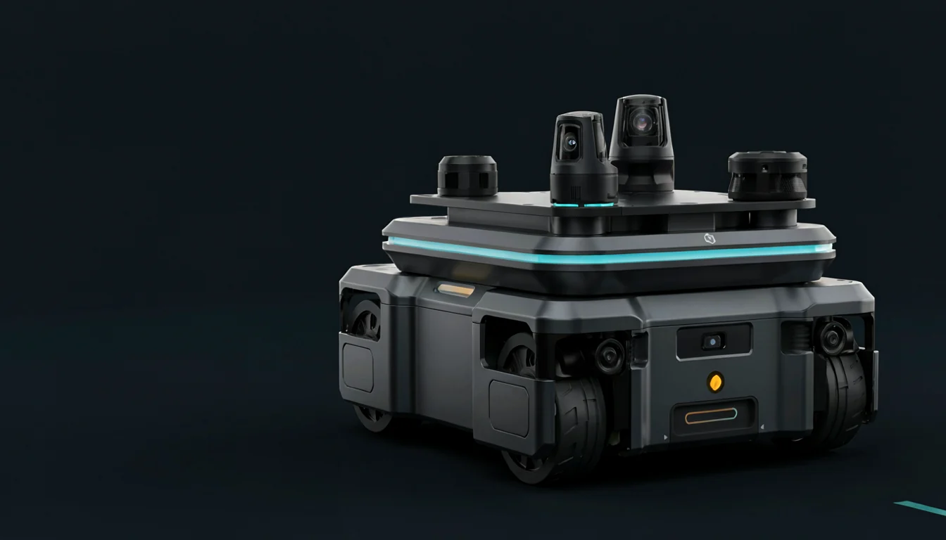
The short answer: do not accept AMR obstacle detection from a lidar range figure. Build a repeatable matrix across object geometry and height, approach direction, vehicle speed and load, sensor installation, and operating environment. Record whether the complete vehicle detects, slows, stops, avoids or enters a defined fault. Safety protective fields, navigation avoidance and site traffic controls interact, but they are not interchangeable evidence.
Separate seeing, deciding and stopping
The public scope of ISO 3691-4:2023 covers driverless industrial trucks—including autonomous mobile robots—and their systems, and states that operating-zone conditions significantly affect safe operation. The ISO page currently marks the 2023 edition for revision and lists a DIS successor, so a project should record the edition it actually adopts rather than treating draft status or a product page as a released requirement. This guide relies only on the public scope; it does not reproduce paid clauses.
NIST's mobile-robotics standards programme treats environmental effects, navigation, object detection and protection, capabilities, and test configuration as distinct A-UGV/AMR work areas. NIST also explains that measurement methods expose sensitivity to environmental and operational parameters. One successful carton-avoidance demonstration therefore represents one combination—not coverage across directions, object geometry, speed, load and site conditions.
Four evidence layers: navigation is not a safety certificate
| Evidence layer | Question | Minimum record | What it cannot replace |
|---|---|---|---|
| Sensor coverage | Did the target enter an effective field of view and produce usable data? | Model, mounting pose, field of view, occlusion, timestamps, health and raw data | Does not prove the vehicle acted correctly |
| Navigation/avoidance | Did perception and planning slow, stop or produce an executable detour? | Detection time, trajectory/velocity command, decision reason, timeout and exit state | Ordinary software is not automatically safety-rated |
| Safety protection | Do safety sensor, field, controller and braking chain meet the safety design? | Field sets, response chain, stop result, reset, validation plan and controlled configuration | Does not solve every navigation or productivity problem |
| Operating zone/task | Do aisles, crossings, doors, racks, people and loads fit the vehicle boundary? | Site conditions, traffic rules, task routes, exception handling and SAT results | Cannot be replaced by one sensor data sheet |
Classify objects by geometry and position, not just material
The NIST mobility-performance programme lists ASTM work on A-UGV environment records, configuration records, defined-area navigation and object sets, and reports completed methods for small-obstacle avoidance and weighted driving. Those public categories support a project-specific object catalogue like the one below. Dimensions, materials and placements must come from the real site and risk assessment—not copied universal thresholds.
- near-floor objects, thin edges, thresholds and reachable negative obstacles;
- pallet feet, rack legs, posts, forks and other narrow or partial targets;
- tables, overhangs, cables and protrusions entering the vehicle or load swept envelope;
- sloped, dark, highly reflective, transparent or mesh surfaces that actually occur in the project;
- targets approaching from front, rear, side, inside a turn and sensor-seam directions;
- people, forklifts, other AMRs and moving doors with representative paths and speeds.
Connect the protective field to the complete stopping result
In its mobile hazardous-area protection example, the SICK microScan3 operating instructions state that the protective field must be long enough for the truck to stop under all relevant conditions. Where driving tests determine it, the manual calls for conditions producing the longest stopping distance, including maximum achievable speed, maximum expected load, maximum load dimensions and influential ground conditions. It also accounts for scanner mounting offset to the leading edge of the truck or load. This vendor example is not a project calculation; it demonstrates why scanning range and worst-combination stopping performance are different claims.
Environment belongs in the matrix too. The outdoorScan3 operating instructions warn that fog, rain, snow, dripping water, insects, leaves or other particles in a protective field can affect the scanner. An indoor project should similarly select only its reachable disturbances—such as dust, contamination, reflectors, lighting change or partial occlusion—and verify diagnostics and degraded behavior rather than constructing irrelevant edge cases.
An eight-step FAT-to-SAT test
- Freeze the vehicle configuration. Record sensor model and firmware, mounting pose, field sets, controller/software versions, braking parameters, wheels, body geometry, top module and maximum load envelope.
- Draw coverage and swept envelopes. Put sensor fields, body/load projection, minimum-turn swept area and mounting occlusion in one coordinate system. Mark front, rear, sides, inside turns and sensor seams for verification.
- Build the object catalogue. Give each real target a controlled ID and record size, shape, material, optical character, height, orientation and placement reference so FAT and SAT can reproduce it.
- Combine speed and load. Cover forward, reverse, turns, lateral motion where supported, empty and representative heavy loads. Select combinations that can change stopping distance or swept envelope within the approved operating range.
- Capture the complete timeline. Synchronize sensor timestamps, detections, trajectory/velocity commands, vehicle feedback and final stop pose. Report first valid detection, action trigger, deceleration and final clearance separately instead of judging video appearance.
- Apply reachable disturbances. Vary real floor, lighting, contamination, reflective background, curtains or congestion. Change one interpretable factor at a time and record environment and cleaning state.
- Inject data faults. Through an approved method, create stale data, partial occlusion, frame/time faults or loss of one sensor. Confirm the vehicle does not continue on expired observations and enters the specified slow, stop or fault state.
- Carry FAT into SAT. FAT proves the controlled matrix; SAT repeats critical combinations in real aisles, crossings, doors, rack edges and task loads. Define regression scope after sensor, wheel, brake, load, field or software changes.
Open-source collision monitoring can add a layer, not elevate a claim
Nav2 Collision Monitor can consume LaserScan, PointCloud, Range or Costmap data and apply stop, slowdown or time-to-collision zones in the robot frame, including velocity-dependent zones. Its documentation also states that this CPU-level node does not provide hard real-time safety certification. It can support navigation-layer response and data-health tests, but it does not replace a designed and validated safety sensor, controller and braking chain.
Safety boundary: this is a sensor-coverage and system-behavior test framework. It does not specify protective-field dimensions, stopping distance, safety integrity or conformity for any AMR. The responsible organization must derive and validate the actual safety design from released standards, vehicle and safety-device manuals, the risk assessment, final configuration and operating-zone conditions.
Frequently asked questions
If lidar range exceeds stopping distance, is safety coverage sufficient?
No. Effective protective range, resolution, mounting offset and occlusion, target characteristics, response time, actual braking, speed, load, floor and the truck/load leading edge still matter. Validate the complete stopping result.
What should be tested after a carton is detected successfully?
Choose reachable low, narrow, elevated, sloped or optically difficult targets from the real site, then cover front, rear, side, inside-turn and sensor-seam approaches. Do not add theoretical objects merely to increase the count.
Can a standard 3D camera or Nav2 Collision Monitor replace a safety scanner?
Not from similar functionality alone. Ordinary perception can support navigation and diagnostics, while a safety function must satisfy the risk assessment, applicable standards, device capability and validated safety chain. Nav2 explicitly states that its CPU node has no hard real-time safety certification.
Why repeat obstacle tests at SAT after FAT passed?
FAT proves behavior in a controlled configuration. SAT introduces the real floor, aisles, racks, doors, lighting, wireless environment, task load and traffic. Repeat the combinations that can change detection, stopping or avoidance.
Sources
These primary sources support the material facts and engineering boundaries discussed above.
- ISO 3691-4:2023 — Driverless industrial trucks and their systems
- NIST — Mobile Robotics Systems Research and Standard Test Methods
- NIST — Mobility Performance of Robotic Systems
- NIST — Navigation Test Method
- SICK — microScan3 PROFINET Operating Instructions
- SICK — outdoorScan3 PROFINET Operating Instructions
- Nav2 — Collision Monitor
Evaluating robot control, bimanual manipulation or a mobile platform?
Talk to Matrix Dimension →